- According to instuctions in the user manual, montage and connections should made by the authorized persons. Do not turn on the device unless a proper connection is established.
- Be sure that the device is de-energized before connecting the device to the line.
- Use dry cloth to clean/remove dust from the device. Don’t use any corrosive material like alcohol and thinner.
- Put the device into use after all connections are completed.
- Don’t open the device box. There is no part exist that the user make any changes on it.
- Keep the device away from the humid, wet, vibrant and dusty ambients.
SIGNAL INPUT

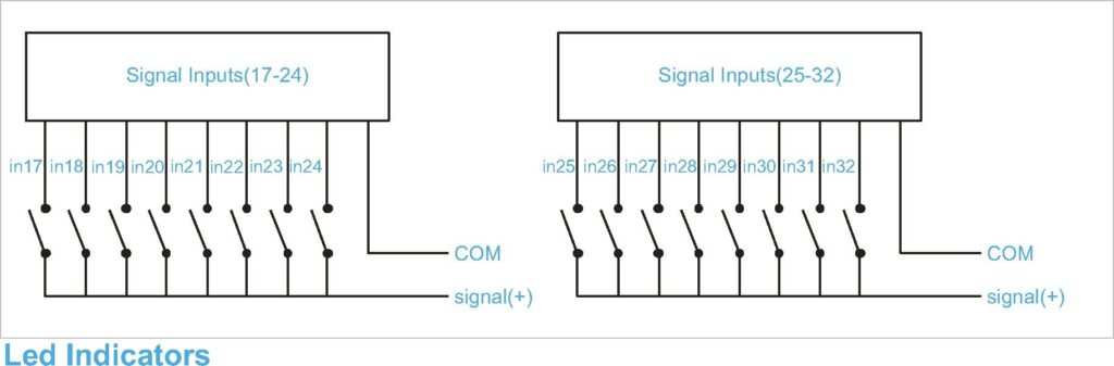
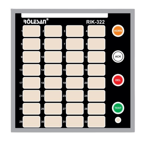
There is 32 led incdicators on this device. These indicators are assigned to related signal input channels. When alarm occur on a channel, related indicator specifies that case of alarm. Led indicators can be lit double colored as red and green. Besides depending on continuity of the signals on the input channels and occurance of the alarm as first or last, flashing mode of the leds can vary.
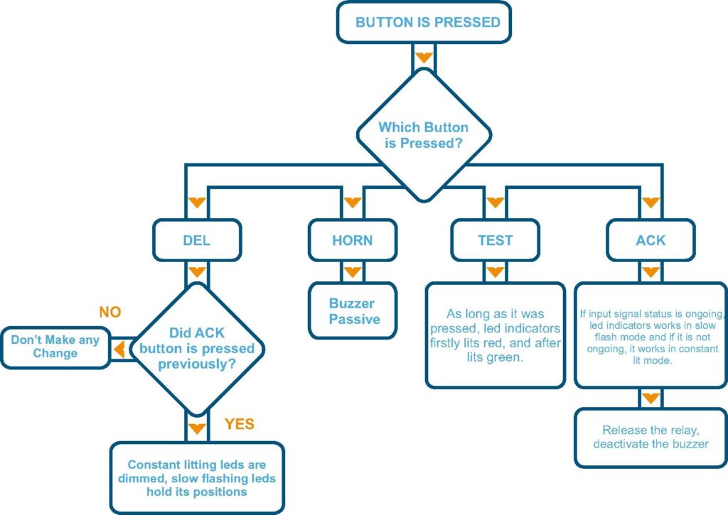
Front Panel Buttons
There are four pieces of buttons situated on the front panel of the device:”HORN”, “ACK”, “DEL” and “TEST”
HORN: This button turns off the buzzer if the buzzer is active.
ACK: This button is used for approving the alarm. When the ACK button is pressed, if the signal situation continuous, fast flashing leds becomes to flash slowly and slow flashing led indicators keep its positions. If the signal situation is not continuous, ralted led indicators lits constant(not flashing).(In LSK mode, this button deactivates the relays but as long as alarm input is active, leds keep to continue litting which belongs to that input channel).
DEL: This button is used for deleting the alarms. When DEL button is pressed, related channels indicators are dimmed if alarms on the channels are approved and signal situation stops.
TEST: This button is used for controlling the device and led indicators are working correctly. As long as TEST button is pressed, led indicators lits as red and green respectively.
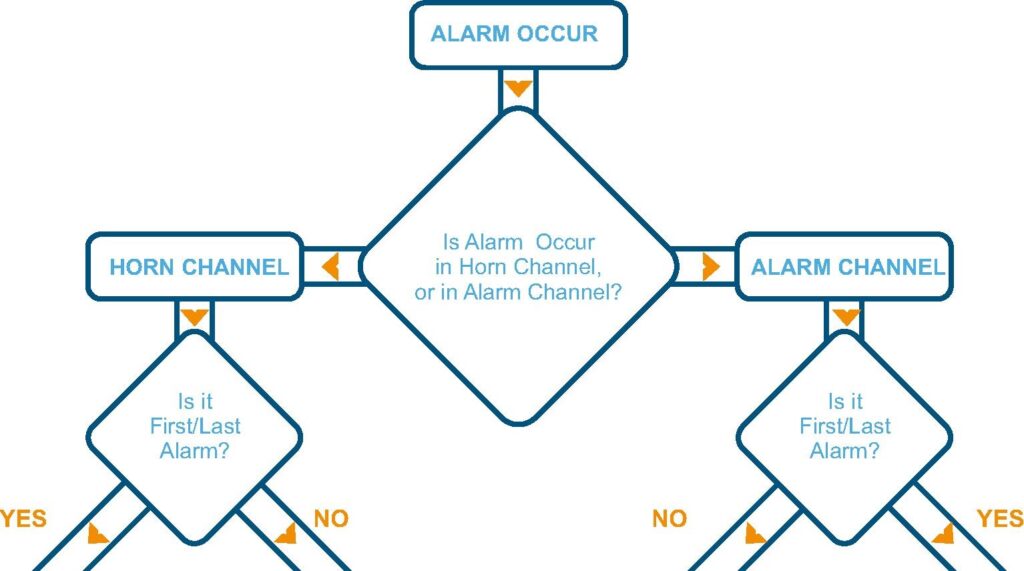
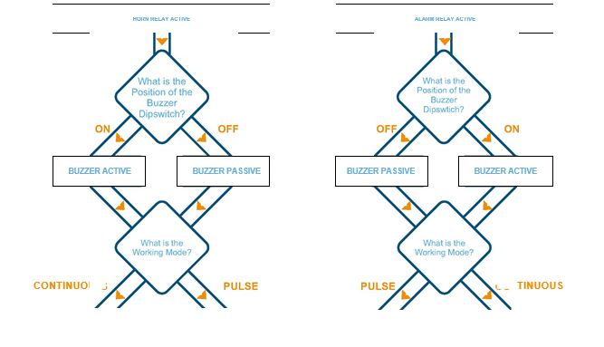
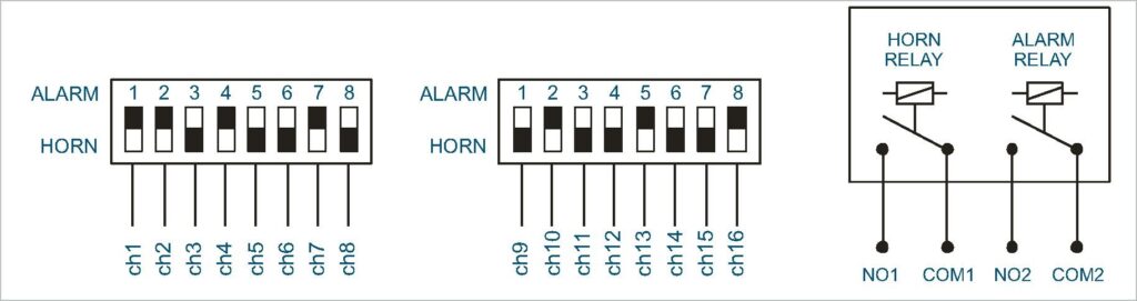
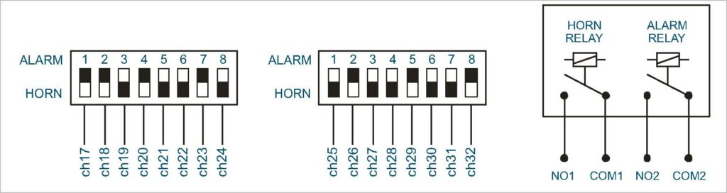
Alarm/Horn Status and Relays
All input channels can be adjusted separately as “ALARM” and “HORN” channel with dipswitches.
Red led indicator is assigned to “ALARM” channels and green led indicator is assigned to “HORN”channels.
Two relay present in the device as “ALARM” and “HORN”. Alarm channels are assigned to the “ALARM” relay and horn channels are assigned to “HORN” relay.
In LSK mode, as long as the channel input is active, device will give output at the end of the delay time.