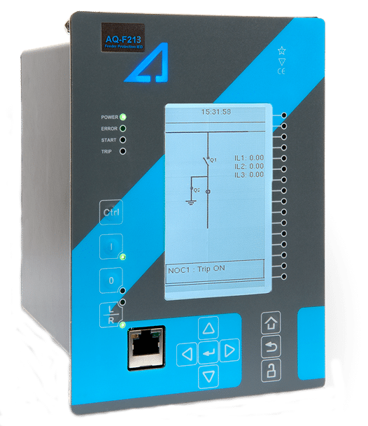
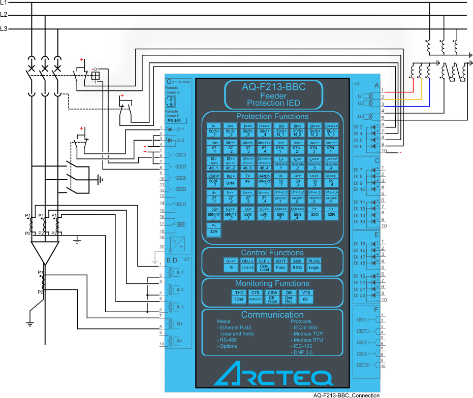
Uygulama Çizim
Dökümanlar
Koruma
Kontrol
Ölçme ve İzleme
İletişim
Donanım
Aksesuarlar
Uygulama Çizim
Dökümanlar
- Download PDF
- AQ 200 Series flyer v2.01 (English)
- AQ 200 Series product catalogue v1.03 (English)
- AQ-F213 Product flyer v1.02 (English)
- AQtivate PRO Flyer v1.00 (English)
- AQ-F213 Instruction manual v2.04 (English)
- AQ 200 series DNP3 device profile v4.00 (English)
- AQ 200 series DWG connection drawings (.zip file)
- AQ 200 series IEC 103 interoperability list v1.00 (English)
- AQtivate 200 Instruction manual v2.02 (English)
Koruma
- Non-directional overcurrent (I>; 50/51) - 4 stages (INST, DT or IDMT)
- Non-directional earth fault (I0>; 50N/51N) - 4 stages (INST, DT or IDMT)
- Directional overcurrent (Idir>; 67) - 4 stages (INST, DT or IDMT)
- Directional earth fault (I0dir>; 67N/32N) - 4 stages (INST, DT or IDMT)
- Negative sequence overcurrent/ Phase current reversal/ Current unbalance (I2>; 46/46R/46L) - 4 stages (INST, DT or IDMT)
- Harmonic overcurrent (Ih>; 50H/51H/68H) - 4 stages (INST, DT or IDMT)
- Circuit breaker failure protection (CBFP; 50BF/52BF)
- High-impedance or low-impedance restricted earth fault/ Cable end differential (I0d>; 87N)
- Overvoltage (U>; 59) - 4 stages (INST, DT or IDMT)
- Undervoltage (U<; 27) - 4 stages (INST, DT or IDMT)
- Neutral overvoltage (U0>; 59N) - 4 stages (INST, DT or IDMT)
- Overfrequency and underfrequency (f>/<; 81O/81U) - 8 stages (INST or DT)
- Line thermal overload (TF>; 49F)
- Resistance temperature detectors (RTD)
- Voltage memory
- Arc protection (IArc>/I0Arc>; 50Arc/50NArc) (optional)
Kontrol
- Number of objects to control and monitor: 5
- Number of indicators to monitor: 5
- Number of setting groups: 8
- Cold load pick-up
- Switch-on-to-fault
- Auto-recloser (0 → 1; 79)
Ölçme ve İzleme
- Phase, sequence and residual currents (IL1, IL2, IL3, I01, I02)
- Current transformer supervision
- Circuit breaker wear monitoring
- Measurement recorder
- Measurement value recorder
- Event recorder (max. 15 000 permanent event records)
- Disturbance recorder (max. 100 records á 5 seconds at 3.2 kHz sampling)
İletişim
COMMUNICATION INPUTS
- RJ-45 100 Mbps Ethernet (front panel, fixed)
- RJ-45 100 Mbps Ethernet and RS-485 (rear panel, fixed)
- 2 x RJ-45 100 Mbps Ethernet with an IRIG-B input (optional)
- 2 x ST 100 Mbps Ethernet with an IRIG-B input (optional)
- 2 x LC 100 Mbps Ethernet (PRP/HSR) (optional)
- RS-232 serial fiber (PP/PG/GP/GG) (optional)
COMMUNICATION PROTOCOLS
- IEC 60870-5-101/104
- IEC 60870-5-103
- Modbus/RTU and Modbus/TCP
- DNP3
- SPA
Donanım
- Current inputs: 5
- Voltage inputs: 3
- Digital inputs (fixed): 6
- Digital outputs (fixed): 5
- Number of empty slots: 3
- Digital inputs: +8/16/24 (optional)
- Digital outputs: +5/10 (optional)
- Milliampere I/O module (4 mA outputs + 1 mA input)
- Arc protection module (4 sensors + 2 HSO + 1 BI)
- Communication media (see "Communication" below)
- External I/O modules (see "Accessories" below)
Aksesuarlar
- AX007 External 6-channel 2-/3-wire RTD input module (pre-configured)
- AX008 External 8-channel thermocouple and mA input module (pre-configured)
- AX009 Raising frame (87 mm)
- AX010 Raising frame (40 mm)
- AX011 Combiflex frame
- AX012 Wall mounting bracket